
In This Issue: 1. Cover Story – Residual Magnetic Field Indicators 2. Special – Don’t Forget the Asset Write Off 3. News – ECHOGRAPH 1095 – LINE CHARTS, B-SCANS & TOFD INSPECTIONS 4. News – Echometer 1077 – New Application Probes
ECHOGRAPH 1095
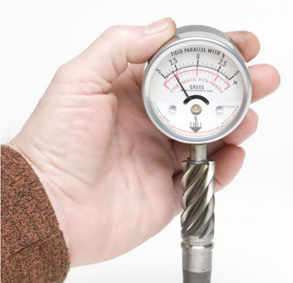
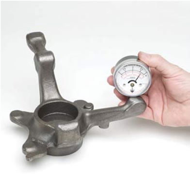
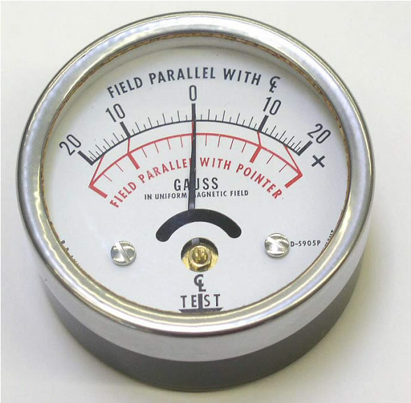
Description: A small magnet, to which an external magnetic field exerts a torque, is mounted onto the revolving axis of the instruments pointer. Another magnet inside the housing keeps the pointer in zero position as long as no external magnetic field is present. The magnetic field intensity is measured at the movement staff location, i.e. on the axis where the revolving magnet is mounted: 16 mm apart from front and rear side of the housing. The axis of the pointer is 16 mm apart from the bottom side of the housing, where the “TEST” mark indicates the edge which should be in contact with a work piece when using the Residual Field Indicator. One end of the pointer axis is visible through the glass. The Residual Field Indicator is equipped with two scales. The upper black scale reads directly in gauss of a uniform magnetic field oriented parallel with the centreline of the instrument scale and the “TEST” arrow. The lower red scale is used in determining the magnitude and direction of an unknown magnetic field by merely orienting the instrument for maximum reading. At such a maximum reading the direction of the field is parallel with the instrument pointer and the magnitude can be read in gauss on the red scale. A (+) deflection of the pointer indicates the TEST edge of the Residual Field Indicator has been presented to a magnetic North pole, a (-) deflection, that is has been presented to a magnetic South pole. (Hint for the earth magnetic field: The geographical North pole is from the magnetic point of view a South pole.)
Available in Ranges of: -5~0~+5 Gauss -10~0~+10 Gauss -20~0~+20 Gauss -50~0~+50 Gauss -100~0~+100 Gauss
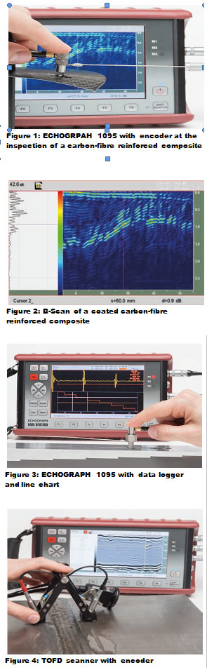
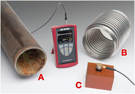
Traditionally, ultrasonic testing is performed by recording an A-scan, showing the echo amplitude as a function of the sound path travel time. The result strongly depends on the inspector’s qualification and skills. Geometry indications could be misinterpreted as flaws and a brief moment of inattentiveness is enough for an indication to slip through. Here the B-Scan can help, especially with difficult inspections. Therefore an encoder is connected to the probe, see figure 1. Solutions are, for example, hand scanners with roller probes. With the encoder, the ECHOGRAPH 1095 is able to assign an A-scan to the respective position in the test volume. While moving the probe linearly, an A-scan is recorded. for each position and plotted in the B-scan against the scan path. Thereby, the A-scan is colour-coded, this means large echo amplitudes are coloured red, while small amplitudes are marked in dark blue, see figure 2. In addition to the determination of amplitude and depth of an indication, as in the A-scan, the B-scan offers the possibility to laterally size an indication. Since the dynamic of an echo along the scan path can be evaluated in the B-scan, the interpretation of a B-scan is also much easier than that of an A-scan. Additionally, the B-scan is suited for a clear documentation of the inspection. In case of weld testing with an angle probe the half-width for lack of fusions and shrink-holes can be sized exactly. Another example would be the capturing of the half-width of a lamination during sheet metal testing with a straight-beam probe. Often the dynamic of a measured value is interesting, e.g. wall thickness, echo amplitude, sound path or velocity. With an encoder and the new data logger, the ECHOGRAPH 1095 is able to record the dynamic and displays it in a line chart for further analysis, see figure 3. For weld inspection with the Time-of-Flight (TOFD) technique, also B-scans are recorded. The TOFD technique uses two broadband angle probes, which emit very short and divergent ultrasonic pulses, one of which acts as a transmitter, while the other is the receiver. Since both probes have to be moved in parallel and synchronously, they have to be fixed in a scanner comprising an encoder, see figure 4. The ultrasonic pulse travels on various paths from the transmitter to the receiver. The lateral wave travels the shortest path along the surface, while the longest path is a V-reflection from the back wall. Discontinuities between surface and back wall create additional signals through diffraction at the crack tips. The TOFD test results are provided in a grey scaled B-scan, formed from A-scans between lateral wave and back wall reflection. From the diffraction signals in the TOFD scan the depth, extent and length of indications can be determined with high precision.
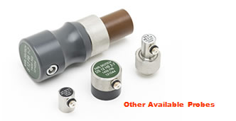
New Application Probes
This causes incorrect results for the measurement, which can easily be corrected by a simple multi-point calibration of the ECHOMETER 1077. With the TR-probe DSE 4.2/4 PB 10 MHz, it is possible to get an echo in the A-scan with the correct wall thickness.
Then, the very short echoes of the back wall echo series (BE-BE-Mode) can be evaluated to determine the wall thickness. In this The transducer SDS 3 PB 6-16 MHz was used. It has an element diameter of 3 mm and enables the testing of wall thicknesses down to 150 μm in steel. Due to its small diameter, this transducer is especially well suited for small contact areas.
Have any questions or like further details?; Ph 02 88503755 or Email |
The Best in Quality Service and Products for Non destructive testing
KK & S INSTRUMENTS
The Best in Quality Service and Products for Non destructive testing